Thursday, November 29, 2012

Dynamic Models and Simulations for Reduced and Approximate Philippine Major Island Power Grids

Since developing the power flow models of Luzon, Visayas and Mindanao, one step forward in these projects is to provide dynamic modeling of the generators, exciters, governors, etc.

I followed the references [1-3] for assuming models for each generation considering fuel types. Also, combined with these good sources, PowerWorld provides default data for the dynamic models including the generic wind generation dynamic models (for NorthWind generation, north of Luzon) and loads (motors and discharge lighting, etc).

For generation using diesel as fuel, I initially modeled the machine as GENSAL but WECC has indicated to use GENTPJ instead for reasons cited in reference [4].

As I'm using PowerWorld, I made advantage of the auto correction of dynamic data and proceeded with the validation of models.

As mentioned in other posts, I simulated flat runs and had the models respond as expected. The following plots are simulated three-phase faults where fault clearing time is in accordance with the Philippine Grid Code and assuming a single-line contingency.

Bus Voltages Plots for Fault on Balintawak 230 kV, tripping Balintawak-Araneta 230 kV Line (Luzon)

Rotor Angles Plots for Fault on Balintawak 230 kV bus, tripping Balintawak-Araneta 230 kV Line (Luzon)

Bus Frequency Plots for Fault on Lugait 138 kV bus, tripping Lugait - Tagaloan 138 kV Line (Mindanao)

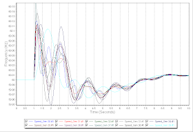
Generator Speed Plots for Fault on Lugait 138 kV bus, tripping Lugait - Tagaloan 138 kV Line (Mindanao)

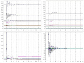
Various Plots for Fault at Quiot 138 kV bus, tripping Quiot-Banilad 138 kV Line (Visayas)

I'm planning to write a full paper on this work and if you are interested in the models or collaborate with me, drop me a message at ebcano@gmail.com.

References:
[1]    IEEE Recommended Practice for Excitation System Models for Power System Stability Studies, IEEE Std 421.5-1992
[2]    IEEE PES Working Group, Hydraulic Turbine and Turbine Control Models for System Dynamic, IEEE Transaction on Power System 7 (1992) 167-174.
[3]    Dynamic Models Package Standard 1. Available: http://www.energy.siemens.com/hq/pool/hq/services/power-transmission-distribution/power-technologies-international/software-solutions/Dynamic_Models_Package_Standard-1.pdf
[4]    Additional Information on GENTPJ Model. Available: http://www.wecc.biz/library/WECC%20Documents/Documents%20for%20Generators/Generator%20Testing%20Program/gentpj%20and%20gensal%20morel.pdf

Monday, November 26, 2012

Modeling FACTS Devices


There are two categories in modeling Flexible AC Transmission System (FACTS) devices in power systems: steady –state modeling and dynamic modeling.

Steady-state

For Unified Power flow Controller (UPFC), you can model this device by inserting a phase shifting transformer (PAR) between two buses connected with a transmission line(s). Since a PAR controls the power transfer by adjusting its tap, this can mimic UPFC response in a given condition. Other implementation [1] includes a bus with a generator and a bus with a load, which are not connected, inserted in a transmission line where the power flow is supposedly controlled.

For a Static Var Compensator (SVC), model a generator without MW output but with MVar (Qmax and Qmin) limits. The model is basically a synchronous condenser but enough to simulate the SVC response. Normally, the output of the SVC is dependent on the bus voltage where it is connected (maintaining a certain magnitude).

For a Thyristor Controlled Static Reactor/Capacitor (TCSR/TCSC), model a series reactor/capacitor along a given transmission line in the power flow case. Note that this is basically a series compensation model and in power flow, the compensation is seen as constant in all throughout the simulation.

In any case, you must assure that no pre-contingency impact violation is produced when you add a FACTS device in the power flow model before running contingency analysis, OPF or locational marginal pricing (LMP) studies.

Dynamics

For SVC, most power system application programs (PSS/E, PSLF, and PowerWorld) apply a Static Var Compensator dynamic model (CSVGN), for example in PowerWorld [2].

For UPFC and TCSR/TCSC, for the above software packages there is no known modeling for dynamic simulations, unless a user model is developed. Most research on dynamic modeling of these devices are implemented in MATLAB or PSCAD/EMTDC.

References:
[1]    A. Kazemi, et al, “A comprehensive load flow model for UPFC and its combination with ESS.” Available: http://www.emo.org.tr/ekler/986405e39c5a796_ek.pdf
[2]   http://www.powerworld.com/files/Block-Diagrams.pdf

Wednesday, November 21, 2012

New Citations


Citing my work on “Utilizing Fuzzy Optimization for Distributed Generation Allocation,” IEEE TENCON 2007:

Citing my work on ““Static Voltage Stability Analysis for Electric Subtransmission System”, http://ebcano.files.wordpress.com/2008/07/microsoft-word-ebcano_vs_0908.pdf, 2008:


Tuesday, November 20, 2012

Reduced and Approximate Models of Philippine Major Island Power Grids


Abstract—The restructuring of electric power industry brings challenges and opportunities among its stakeholders. Economic and engineering analyses brought forth by these changes are usually tested on power system test models to study different strategies. In a developing country, like the Philippines, where commercial and security concerns may prevent the availability of these test systems, the involvement of research and academic communities’ maybe limited. This paper reports the development of reduced and approximate power system models for major islands in the Philippines using publicly available data which can be utilized for research and academic purposes.

Index Terms—Electric power test systems, interconnected power systems, electric power system modeling.

Download the full paper here.

Sunday, November 11, 2012

Integrating Computer Simulations in Electrical Engineering Courses


Abstract— At the deregulation of electric power industry, technical and value-based studies for planning and operations of power systems as outlined in electricity regulatory codes should be integrated in electrical engineering programs and promote the present scenario by undertaking power systems applications and incorporate computer simulations to stimulate students' interest and increase their insights with the on-going deregulation of the industry.  This paper provides experience of incorporating computer applications and simulations in undergraduate and graduate programs considering present curriculum and subject offerings. 

Index Terms— electrical engineering education, computer simulations, power systems

Download the full paper here.

Friday, November 2, 2012

New England 39 Bus Test System

The New England 39 bus test system is a power system test system usually utilized for dynamic simulations test and research. It is believed that this is an actual equivalent system of the New England grid in 1960s [1].


The data I utilized here comes from [2], where the power flow and dynamics data were given in PSS/E v29 format which were loaded into PowerWorld. The data has 1 kV base voltage in all buses which I changed to 345 kV to reflect the New England system voltages. In the PowerWorld's transient stability data validation (this is very cool!), I accepted the corrections identified in the dynamic data, mostly are time constant depending on the time step being studied.

Normally in stability simulations, it is imperative to run a no fault simulation or what they call flat run to verify that dynamic models are behaving in a manner without disturbance thus expecting flat plots of parameters.

Generator angles for no fault simulation.

A stub fault is another practical test if the response of the dynamic models is correct for a simple and fast fault disturbance. Here are example plots from a stub fault at bus 1 at 1.0 seconds and cleared after 0.1 seconds without tripping any line.

Generator angles for stub fault simulation.

Generator speed for stub fault simulation.

Bus frequency for stub fault simulation.

Bus voltages for stub fault simulation.

If you want the New England 39 bus test system, email me at ebcano@gmail.com.

References:
[1] Power Systems Test Case Archive. Available on-line: http://www.ee.washington.edu/research/pstca/dyn30/pg_tcadyn30.htm
[2] Pablo Ledesma, New England Test System, IEEE 39 Bus System, 10 generators, in PSS/E format (version 29). Departamento de IngenierĂ­a ElĂ©ctrica Universidad Carlos III de Madrid. Available on-line: http://electrica.uc3m.es/pablole/new_england.html